ABOUT
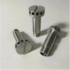
Custom Molybdenum Parts Processing -Molybdenum Screw
Grade: Mo1, MLa, TZM
Implementation standard: GB/T3877-83
Specifications: processing according to drawings

Applications: (1) Used for manufacturing electric vacuum devices and electric light source parts
(2) Suitable for processing ion implantation parts
(3) Used as high-temperature heating elements and high-temperature structural parts
(4) Used as electrodes for furnaces in the glass and refractory fiber industries, working in 1300℃ glass melt with long service life
(5) Used as electrodes in the rare earth industry
Molybdenum processing parts characteristics:
1. High melting point and good high temperature resistance
The melting point of molybdenum plate reaches 2620℃, which is one of the highest melting points among metals. This makes molybdenum plate have excellent stability and corrosion resistance in high temperature environments, and can withstand applications under extreme high temperature conditions, such as furnaces, spacecraft components and high-temperature molten metal containers.
2. High Density and Excellent Mechanical Properties
Molybdenum parts have a high density of 10.2 g/cm³, resulting in excellent mechanical properties such as high strength, high hardness, and good tensile strength. This makes molybdenum parts widely used in electronic components, vacuum equipment, the chemical industry, and aerospace.
3. Excellent Thermal and Electrical Conductivity
Molybdenum special-shaped parts have excellent thermal and electrical conductivity, among the best among metals. This makes molybdenum parts play an important role in electronic devices, power generation equipment, thermal instrumentation, and fiber optic communications.
4. High Corrosion Resistance and Stability
Molybdenum parts exhibit excellent corrosion resistance and stability in most chemical media, demonstrating excellent chemical stability. This has led to their widespread application in the chemical industry, medical devices, optical instruments, and environmental protection.
Thread Turning of Molybdenum Alloy Parts

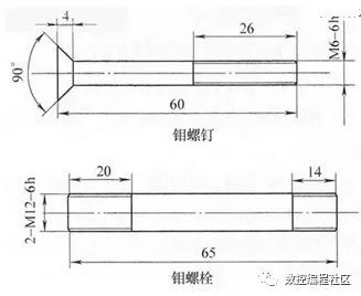
Molybdenum alloys have high strength and hardness, but poor toughness, are brittle, and prone to fracture, resulting in poor machinability. However, due to their high melting point, low density, and low thermal expansion coefficient, they are often used in the manufacture of various high-temperature components in the aerospace and aviation industries. Two molybdenum alloy parts, a molybdenum screw and a molybdenum bolt, are shown in the accompanying figure. The incoming blanks were hot-rolled Ø16mm molybdenum alloy steel bars. During processing, it was discovered that the material had low density and very high surface hardness, likely due to residual hardness from annealing. The hardness within the surface layer remained high, with poor toughness and slow thermal conductivity. Using ordinary high-speed steel or carbide cutting tools was extremely difficult. First, the front and rear cutting edges and tips of the cutting tools wore rapidly. Despite adding cutting fluid and repeatedly testing different cutting parameters under normal conditions, satisfactory results were unsatisfactory. External cylindrical inserts typically needed to be replaced after machining no more than four parts. Second, even with the slightest wear, the parts began to slag. This slag was observed during faceting, parting, and threading. While external cylindrical machining and end-face machining can generally meet the design requirements, provided the finishing tool remains sharp, threading can inevitably cause chipping.
In actual machining, M6 thread turning results are poor, with thread segments often breaking off at the end. This is unavoidable, requiring die machining. For M12 threading, high-speed dual-tool CNC lathes achieve excellent results.
Because both parts are relatively long, threading is typically performed after turning the external cylindrical surface, then cutting, and then flattening the overall length. Since the process documentation prohibits center holes for both M6 screws and M12 bolts, flattening the center hole is also required at the end of horizontal lathe machining. CNC lathe machining utilizes a segmented approach, eliminating the need for drilling a center hole. The Ø12mm external diameter (M12 large end diameter) is segmented and then cut off; the Ø6mm external diameter (M6 large end diameter) is segmented and then tapered and then cut off. The procedures are relatively simple and will be omitted here. It’s important to note that machining a Ø6mm outer diameter to Ø5.85-Ø5.93mm significantly facilitates threading. If the outer diameter is larger than Ø5.93mm, the threading allowance is large, which can easily lead to thread chipping, missing threads, and other incomplete thread forms. If the outer diameter is smaller than Ø5.85mm, the amount of extrusion deformation during threading is limited. If the machine tool dimensions fluctuate, this can easily cause the M6 thread’s large end dimension to approach the limit or exceed tolerances. Furthermore, when cutting off, the total length allowance should be at least 1.5mm. This prevents blunting of the cutting tool or poor chip removal, which could cause chipping at the root of the part (the screw), making it impossible to repair even after the end face is flattened. This means that the part will still have chipping defects after flattening.
For machining the outer diameter and overall length of these two parts, use YG6 or YG8 as the material grade for ordinary carbide tools. The grinding angle should be similar to that used for semi-finishing stainless steel tools. If possible, using machine-clamped tools or coated tools will yield better results. Coated tools are generally classified as physical vapor deposition (PVD) or chemical vapor deposition (CVD). Compared to traditional carbide tools, coated tools offer significantly improved strength, hardness, and wear resistance. They can achieve high-speed cutting for materials with a hardness below 55 HRC. When machining the external diameter of these two types of parts, either PVD or CVD can be used, with CVD inserts being slightly more effective.
Cutting parameters: Speed 600-900 rpm. Cutting depth 0.3-0.6 mm. Feed rate 0.2-0.3 mm/r. Due to the high cutting heat generated, a water-soluble cutting fluid should be used primarily for cooling.
After machining the outer shape and overall length, threading should begin. When machining M6-6h threads, accurate chuck centering is essential. Avoid using a die holder if possible; a threader is preferred for hard and brittle materials. Even a slight misalignment between the centerline of the die held by the die holder and the centerline of the workpiece can easily lead to breakage or chipping of the part. A threading tool can compensate for misalignment between the two centerlines. Industrial soybean oil, a lubricant used for threading, is used as the primary lubricant.
When machining M12-6h threads, the high torque during threading makes clamping difficult, leading to workpiece spin. More seriously, due to the material’s characteristics, the threads suffer from severe chipping defects and incomplete tooth profiles. Using a die is not an acceptable method for machining. Using a threading tool on a horizontal lathe with a high-speed steel (W18Cr4V) tool at a low speed (50 rpm) quickly reaches tool wear limits, resulting in unsatisfactory cutting results. Tests on CNC lathes using welded carbide tools such as YG8, YG6, and YW1, as well as coated tools such as PVD and CVD, at speeds below 1200 rpm also yielded unsatisfactory results.
Based on the experimental results and material properties, we decided to test a new international machining method: high-speed, fast-travel, small-knife cutting. Due to material properties and tool wear, thread cutting was performed using a challenging high-speed (2100 rpm) dual-tool roughing and finishing method. After comparing threading command formats, G34 (variable-pitch threading command) and G32 (single thread cutting command, requiring separate input and exit commands, which was too cumbersome) were eliminated. Instead, G92 and G76 programming were used for trial runs. The machining procedure is as follows:

Keyword:
We Exist to Make Your Projects Successful
Fill out the form below and someone from our team will be in touch with you!
FOTMA Delivers Professional Ultra-Dense Solutions, Lighter on Cost, Heavier on Performance.
Hubei Fotma Machinery Co. Ltd.
Wechat / Whatsapp / Mobile:
+86 13995656368, +86 13907199894
Tel: +86-27-67845266
Email: bunny@fotma.com, export@fotma.com
Address: Guanggu Avenue 52#, Hongshan, Wuhan,
Hubei province, P.R.China. 430074